When an application requires protection against the elements the “Climate-Guard” service door is the solution. Rain, dust and wind are kept at bay by vinyl weatherstripping at the footpiece, guides and hood. Designed for sizes up to 30′ wide and 30′ high these doors are constructed to weather the storm and provide years of worry free service.
All R&S doors are designed to withstand up to 80 mph winds and can be upgraded for more severe weather conditions. Curtains can be ordered in standard grey or in tan with contrasting black guides and footpiece. A galvanized steel finish is also offered providing the look and protection of stainless steel without the cost.
Part 1 General
1.01 Summary
A. Service doors excluding design, construction and preparation of openings; finish or field painting; access panels; electrical wiring, conduit, wire, fuses and disconnect switches.
1.02 Performance
A. Windload: Service doors are designed to withstand a minimum 20 PSF windload.
B. Usage: Service doors are designed to operate a minimum of 20,000 cycles.
Part 2 Products
2.01 Materials
A. Manufacturer: R & S Manufacturing, model W ___
B. Mounting: Interior or exterior face of wall or between-jamb.
C. Operation: Chain hoist is standard; push-up (small sizes), awning crank, crank box or motor operation are optional.
D. Curtain: Interlocking type 25 flat slats are roll formed from galvanized steel coil. Gage of slats is as required to meet windload. Endlocks are riveted to slats to maintain curtain alignment. Windlocks are riveted to slats when required to meet windload. Bottom of curtain is reinforced by an extruded aluminum or double steel angle footpiece with astragal.
E. Guides: Steel channels or structural steel angles form curtain guides and are bolted to structural steel wall angles. Sizes of guides are as required to retain curtain under windload. Windlock bars are provided when winlocks are required to meet windload. Vinyl guide weatherstripping against the flat faced side of the slats is standard (wool pile, brush, or weatherstripping on both sides of the curtain are optional).
F. Brackets: Steel plate brackets are bolted to wall angles to support curtain and barrel and provide mounting for hood.
G. Barrel: Minimum 6″ diameter steel pipe houses torsion spring assembly and supports curtain with a maximum deflection of .03 inch per foot of width. Torsion springs are mounted on a continuous cold rolled steel shaft, adjustable by a tension wheel outside one bracket.
H. Hood: Formed from minimum 24 gage galvanized steel sheet, reinforced with tip and bottom flanges to limit defection. Internal vinyl hood baffle is standard. Intermediate support is provided when required.
I. Locking: Chain lock with chain operation and slidebolt locks with push-up or crank operation.
Part 3 Execution
3.01 Installation
A. Service doors are to be installed by an R & S authorized representative in accordance with R & S installation instructions.
(1) Standard design will allow the rolling door to be operable after having been subjected to a uniform constant load of 20 PSF. Curtain slat deformation may occur and there is no guarantee of operability while under load unless such a requirement is stated by the specifier. Windload forces acting on the rolling door slats may cause severe loadings at the jambs. The building door jamb construction (walls, steel structure, etc.) must be designed to withstand the anticipated loads.
(2) Frequency requirements must specify for the door operator and all components a fixed number of cycles for an expressed period of time and include a sealed counter device. A cycle is defined as an action on the door from fully closed, to the fully open, and returned to the fully closed position.
Climate Guard Options
Increased Windload Capacity: Curtain designs to withstand windloads exceeding 20PSF
High Cycle Construction: Designs to provide up to 150,000 operating cycles or maximum possible in design.
Vision Lites: Single or multiple 3″ wide cutouts, covered with acrylic.
Powder Coat Finish: Available on all exposed surfaces, powder coating is a durable and decorative finish for steel or aluminum surfaces that provides longer life and requires less maintenance than a standard finish. Available in a variety of colors. Consult factory for color selection, applications and limitations.
Galvanized Finish: Hot dip Galvanizing available on footpiece, guides and brackets
Sloped Footpiece: For door openings on a slope
Cylinder Locks: Installed on footpiece or guide.
Pass Door: 3′-0″ x 7′-0″ x 1-3/4″ thick hollow metal grey primed (black optional) door in a steel frame for access through the curtain when closed; frame is hinged to guide and swings clear to allow use of entire door opening when curtain is raised; Standard hardware includes lever lock with optional deadbolt; handicap option, custom sizes, windows and special hardware available.
Tubular Motor Operator: Motors completely contained within the barrel can be provided for heavy duty service doors up to 144 sq ft in limited usage applications. Only the manual crank override is visible outside the bracket. The units are available in 115 volt/single phase with constant contact one button or key switch control. They can also be provided with a low voltage controller when options such as a 3 button station, reversing edge or timer are required.
|
|
|
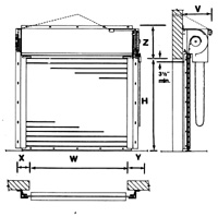
| Opening Width ‘W’ |
X” |
Y” |
| Up to 15′ |
6 |
8 |
| 15′-24′ |
7 |
9 |
R/H chain operation as shown – reverse ‘X’ & ‘Y’ for L/H
|
|
|
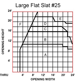
| Area |
Z” |
V” |
| A |
20 |
16-3/4 |
| B |
22 |
17 |
| C |
23-1/2 |
18-1/2 |
| D |
25-1/2 |
20-1/2 |
| E |
29-1/2 |
24-1/2 |
| F |
Consult
Factory |
Consult
Factory |
Reduce ‘Z’ by 2″ with top hood flange turned down
|
|
| Type 25 Large Flat Slat |
Type 18 Small Flat Slat |
 |
 |
Steel slats are galvanized per ASTM standards, treated for paint adhesion and pre-finished before forming with a prime coat and baked-on grey or tan polyester top coat.
By Method of Operation – Face of Wall Mount
WFP – Push-Up
WFP – Push-up
WFC – Chain
WFT – Thru-wall-chain
WFA – Awning Crank
WFB – Crank Box
WFM – Motor
For Between-Jamb Mount, change letter ‘F’ to ‘J’