
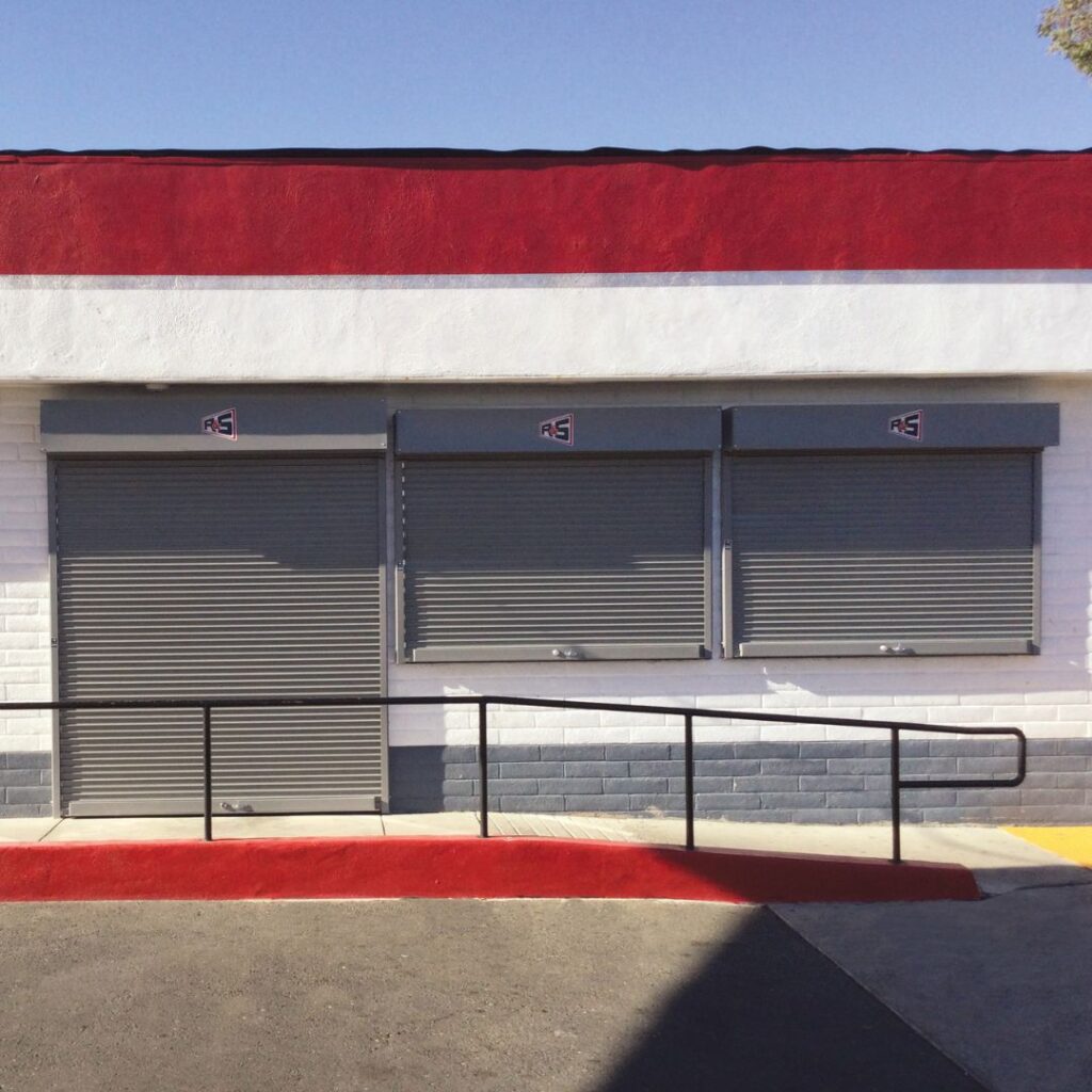
R&S Steel and Stainless Steel Doors combine strength and durability with compact design and neat appearance. Although primarily utilized as a closure on counter openings, these doors may also be used on openings large enough to provide walk-thru or drive-thru access.
Counter doors can be modified in construction to meet steel service door requirements up to 16 feet wide, 10 feet high at a maximum of 144 square feet.
Counter Doors come with a 2 year/ 20,000 cycle warranty. See Warranty Page for details.
Specifications
1.01 Summary
A. Counter doors excluding design, construction and preparation of openings; finish or field painting; access panels; electrical wiring, conduit, wire, fuses and disconnect switches.
Part 2 Products
2.01 Materials
A. Manufacturer: R&S Manufacturing, model N ___, model SN ___ (for stainless).
B. Mounting: Face of wall or between-jamb.
C. Operation: Push-up to 14′ wide and awning crank on larger sizes is standard (awning crank should be considered when doors are to be operated over a deep counter or over 7′ high). Chain hoist or motor operation are optional.
D. Curtain: Interlocking type 18 flat slats are roll formed from (galvanized steel) (stainless steel) coil. Endlocks are riveted to slats to maintain curtain alignment. Bottom of curtain is reinforced by a (single angle) (tubular) footpiece of material matching slats, with astragal.
E. Guides: Box shape guides are formed from (steel) (stainless steel).
F. Brackets: Steel plate brackets are bolted to guides to support curtain and barrel and provide mounting for hood.
G. Barrel: Steel pipe houses torsion spring assembly and supports curtain with a maximum deflection of .03 inch per foot of width. Torsion springs are mounted on a continuous cold rolled steel shaft, adjustable by a tension wheel outside or inside one bracket.
H. Hood: Formed from 24 gauge (galvanized steel ) (stainless steel) sheet, reinforced with top and bottom flanges to limit deflection.
I. Locking: Slidebolt locks on single angle footpiece and cylinder lock on optional tubular footpiece.
2.02 Finish
A. Galvanized steel slats and hoods are pre-finished with a baked on grey polyester primer before forming. Steel footpiece, guides and brackets receive one coat of rust inhibiting grey primer. Exposed stainless steel provided with #4 finish.
Part 3 Execution
3.01 Installation
A. Counter doors are to be installed by an R & S authorized representative in accordance with R&S installation instructions.
Options
Increased Windload Capacity: Curtain designs to withstand wind loads exceeding 20PSF.
High Cycle Construction: Designs to provide up to 50,000 operating cycles or maximum possible in design.
Vision Lites: Single or multiple 3″ wide cutouts, open for ventilation or covered with acrylic.
Sloped or Stepped Footpiece: To accommodate special sill conditions.
Cylinder Locks: Key or thumbturn cylinder lock installed on footpiece or guide for added security and convenience.
Galvanized Finish: Hot dip galvanizing on footpiece, guides and brackets.
Powder Coat Finish: Available on all exposed surfaces, powder coating is a durable and decorative finish for steel or aluminum surfaces that provides longer life and requires less maintenance than a standard finish. Powder coating is available in a variety of colors for use on many products. Consult factory for color selection, applications and limitations.
Tubular Motor Operator: Motors completely contained within the barrel can be provided for counter doors in limited usage applications. Only the manual crank override is visible outside the bracket. The units are available in 115 volt/single phase with constant contact one button or key switch control. They can also be provided with a low voltage controller when options such as a 3 button station, reversing edge or timer are required.
Clearance requirements
| Area | Headroom | Tension Side Room | Power Side Room Push Up | Power Side Room Crank |
|---|---|---|---|---|
| A | 12″ | 4-1/4″ | 2-1/4″ | 4-1/4″ |
| B | 14″ | 4-1/4″ | 2-1/4″ | 4-1/4″ |
| C | 12″ | 4-1/4″ | X | 4-1/4″ |
| D | Consult Factory | Consult Factory | Consult Factory | Consult Factory |
2) Reduce Tension Side Room by 2″ with inside tension
Door Guide, Slat & Footpiece Details
Face of Wall Mounting Guide Detail

Tubular Footpiece Detail

Between Jamb Mounting Guide Detail
Angle Footpiece Detail

#18 Small Flat Slat
Model Designations
Steel Counter Door
NFP – Push-Up
NFA – Awning Crank
NFC – Chain
NFM – Motor
Stainless Steel Counter Door
SNFP – Push-Up
SNFA – Awning Crank
SNFC – Chain
SNFM – Motor
For Between-Jamb Mount, change letter ‘F’ to ‘J’.